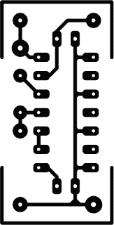
This little circuit is invaluable for quick go/no-go testing of just
about any remote control transmitting infra-red (IR) light. The tester
is battery-powered, built from just a handful of commonly available and
inexpensive parts, and fits in a compact enclosure. Schmitt trigger gate
IC1f is used as a quasi-analogue amplifier with, unusually, an
infra-red emitting diode (IRED) type LD274 acting as the sensor element.
An R-C network, C1-R2, is used at the output of the gate because all IR
remote controls transmit pulse bursts, and to prevent the output LED,
D2, lighting constantly when day-light or another continuous source of
IR light is detected.
This creates a useful ‘quick test’ option: point the tester at direct
daylight, and the indicator LED should light briefly. The sensitivity of
the tester is such that IR light from remote control is detected at a
distance of up to 50 cm. The circuit is designed for very low power
consumption, drawing less than 1 mA from the battery when IR light is
detected, and practically no current when no light is detected. Hence no
on/off switch is required. The construction drawing shows how the
tester may be ‘cased’ using a small ABS case from Conrad.
COMPONENTS LIST
Resistors:
R1,R2 = 10MW
Capacitor:
C1 = 10nF
Semiconductors:
D1 = LD274 (Siemens)
D2 = LED, 3mm, low-current
IC1 = 74HC14
Miscellaneous:
Bt1 = 3V Lithium cell with solder tags, e.g.type CR2045 (560 mAh)
COMPONENTS LIST
Resistors:
R1,R2 = 10MW
Capacitor:
C1 = 10nF
Semiconductors:
D1 = LD274 (Siemens)
D2 = LED, 3mm, low-current
IC1 = 74HC14
Miscellaneous:
Bt1 = 3V Lithium cell with solder tags, e.g.type CR2045 (560 mAh)


Tidak ada komentar:
Posting Komentar