Tampilkan postingan dengan label Alat_Ukur. Tampilkan semua postingan

Selasa, 24 September 2013

ESR Capasitance Meter


File Hex
Klik  Disini


Capacitance
Capacitor Quality
uF 
Very high 
High
Normal
Low
Very low
1.0 
2.000 
5.000 
12.500 
31.250 
78.125 
2.2 
1.125 
2.812 
7.030 
17.574 
43.936 
4.7 
0.646 
1.616 
4.039 
10.098 
25.244 
10 
0.372 
0.931 
2.328 
5.819 
14.548 
22 
0.209 
0.524 
1.309 
3.273 
8.181 
47 
0.120 
0.301 
0.752 
1.880 
4.701 
100 
0.069 
0.173 
0.433 
1.084 
2.709 
220 
0.039 
0.097 
0.244 
0.609 
1.523 
470 
0.022 
0.056 
0.140 
0.350 
0.875 
1000 
0.013 
0.032 
0.081 
0.202 
0.504 
2200 
0.007 
0.018 
0.045 
0.113 
0.284 
4700 
0.004 
0.010 
0.026 
0.065 
0.163 
10000 
0.002 
0.006 
0.015 
0.038 
0.094 

Very Accurate Small L/C Meter


Beli  Disini

Cara Kerja Rangkaian:
  1. Pada saat switch di ON-kan, maka sesaat PIC akan mencatat frekuensi osilasi F1 rangkaian OSC dengan rumus (i), lihat pada ilustrasi. Untuk menyelesaikan persamaan tersebut masih dibutuhkan variable tambahan.
  2. PIC akan mengaktifkan reed-relay untuk melakukan kalibrasi otomatis. Pada saat kalibrasi akan diperoleh frekuensi osilasi F2 dengan persamaan (ii), dimana frekuensi ini berbeda dengan frekuensi F1, karena ada tambahan Ccal, misal nilai Ccal = 1000pf dengan toleransi 2%, maka asumsinya adalah Ccal = 1020pf.
  3. Berbekal dengan variable yang ada yaitu F1, F2 dan Ccal diatas, maka kita akan mendapatkan nilai L1 dan C1, melalui rumus (iii) dan (iv). Nilai F1, L1 dan C1 tersebut kemudian disimpan oleh PIC dalam memory.
  4. Selanjutnya LC Meter akan mengirimkan pesan bahwa ia siap untuk melakukan pengukuran.
  5. Misal pengukuran lilitan Lx, maka switch pengukuran harus dipindahkan ke pengukuran L, akan diperoleh frekuesni osilasi akibat adanya serial L1 + Lx sebesar F2 yang ditunjukkan dengan rumus (v). Dengan mensubstitusikan nilai L1 dan C1, ke rumus (v) tersebut, maka nilai Lx dapat diselesaikan dengan rumus (vi).
  6. Demikian juga halnya pengukuran Cx, maka switch pengukuran harus dipindahkan untuk mengukur C, akan diperoleh frekuensi osilasi akibat adanya serial C1 + Cx sebesar F2, ditunjukkan oleh rumus (vii). Dengan cara yang sama, maka Cx dapat diperoleh dengan persamaan (viii).
  7. Proses perhitungan tersebut dilakukan periodik oleh PIC, sehingga hasil pembacaan selalu terupdate ke LCD.

Langkah-langkah testing dan kalibrasi LC Meter:
  • Cek kembali apakah semua komponen pada tempat yang benar.
  • Cek kembali semua kaki komponen telah tersolder sempurna, dan tidak ada jalur PCB yang saling terhubung secara tidak sengaja.
  • Cek kembali posisi kaki diode dan 7805, jangan sampai terbalik atau salah.
  • Jangan lupa – IC PIC yang dibeli dari toko belum terisi program, Anda harus meload program kedalamnya, bila tidak maka rangkaian tidak akan bekerja.
  • Nyalakan catuan dengan hati-hati. Arus yang dikonsumsi oleh rangkaian seharusnya kurang dari 20mA. Jika anda tidak melihat apapun di layar LCD, sementara semuanya telah dicek kembali dalam keadaan OK, coba lakukan adjusting pada trimpot yang mengatur kekontrasan LCD. Jika trimpot ini diset terlalu lemah, maka karakter tidak akan terlihat pada layar LCD. Jika karakter sudah terlihat, pada saat dinyalakan seharusnya akan terlihat pesan “Calibrating”, kemudian C=0.0pF (atau nilai lain sampai dengan +/- 10pF).
  • Biarkan beberapa saat rangkaian dalam kondisi aktif untuk pemanasan, kemudian tekan tombol “zero” untuk memaksa rangkaian melakukan re-Calibration kembali. Display sekarang seharusnya menunjukkan nilai C=0.0pF.
  • Hubungkan kapasitor standar yang memiliki akurasi nilai baik. LC meter seharusnya membaca nilai kapasitor tersebut mendekati dengan nilai nominalnya (dengan error +/-10%).
  • Untuk menaikkan pembacaan kapasitansi, hubungkan jumper dengan tanda “4” pada diagram dibawah. Sementara untuk menurunkan pembacaan kapasitansi, hubungkan jumper dengan tanda “3” pada diagram dibawah. Ketika pembacaan sudah mendekati nilai nominal kapasitor standar, lepaskan jumper. PIC akan mengingat hasil kalibrasi tersebut. Anda dapat mengulang proses kalibrasi tersebut sebanyak yang anda suka (EEPROM PIC membatasi sampai dengan 10.000.000 kali).
  • Jika terjadi kejanggalan pada LC meter, anda dapat menghubungkan jumper “1” dan “2” untuk mengecek frekuensi dari oscillator. Hubungkan jumper “2” untuk mengecek frekuensi free running dari oscillator disebut dengan “F1”. Nilainya harus ditampilkan sebagai 00050000 +/- 10%. Jika ternyata nilainya terlalu tinggi (mendekati 00065535), maka LC meter akan mengalami overflow dan memberikan pesan error. Jika nilainya terlalu rendah (misal dibawah 00040000), anda akan kehilangan akurasi pengukuran. Hubungkan jumper “1″ untuk mengecek frekuensi kalibrasi yaitu “F2”. Nilainya harus berkisar 71% +/- 5% dari nilai “F1″ yang diperoleh dari menghubungkan jumper “2″ diatas.
  • Beberapa pengguna mungkin ingin melakukan adjustment terhadap induktor sehingga F1 mendekati 00060000 untuk mendapatkan akurasi maksimum dari LC meter. Maka, indultor “L” dengan nilai 82uH dianjurkan untuk kepentingan tersebut, dibandingkan dengan menggunakan induktor dengan nilai 100uH.
  • Jika meter menunjukkan nilai mendekati 00000000 untuk F1 dan/atau F2, lakukan pengecekan ulang terhadap semua perkabelan disekitar switch L/C, hal ini menunjukkan bahwa oscillator berhenti bekerja.
  • Fungsi pengukur induktor secara otomatis akan terkalibrasi, ketika anda melakukan kalibrasi dengan menggunakan kapasitor standar diatas. Anda bisa mencoba menghubungkan kedua terminal pengukur, maka pembacaan “L” seharusnya memberikan nilai Nol.
 File Hex
 klik Disini

Kamis, 13 Desember 2012

Stroboscope Uses White LEDs

This stroboscope circuit uses 16 high-brightness white LEDs in a torch housing and it provides a signal output to a frequency counter to provide a rev counter display. IC1 is 555 astable multivibrator and it provides a signal to IC2, a 4046 phase lock loop. IC2 and the two 4017 Johnson decade counters, IC3 & IC4, make up a frequency multiplier with a factor of 60 (IC3 divides by 10 while IC4 divides by six). The multiplied frequency is taken from the VCO (voltage controlled oscillator) output of IC2 at pin 4 and this becomes the signal to drive the frequency counter. Its output reading is the speed of the shaft being measured in RPM. A narrow positive-going pulse train to turn on Q1 and the LEDs is obtained from pin 3 of IC4. This has the advantage of giving a much sharper marker line (on the shaft) illumination. The unit can be powered from a 12V 500mA plugpack or a suitable battery.

Editorial note:
At switching frequencies above 100Hz (6000 RPM) the persistence of the phosphor of the white LEDs will make the circuit ineffective. To run the circuit at much higher frequencies, substitute LEDs without phosphors; eg, red, green or yellow or a mixture of these).

Selasa, 11 Desember 2012

Mains Frequency Monitor

Here is a simple frequency counter designed to monitor the 240VAC mains supply. It as a frequency range of 0-999Hz, so it could also be used with 400Hz equipment. Standard TTL/CMOS logic is employed for the counters and display drivers, while an ELM446 (IC1) generates accurate 1Hz pulses for gating. This device utilizes a 3.579545MHz crystal for its timebase, as commonly found in TV and video circuits and even on old PC motherboards.


A Very Simple LED Tester

This simple LED tester consists of a current source with a potentiometer that can be used to adjust the current. The current source is implemented using a type TL081 opamp. The output current of the opamp flows through the diode and R2. The voltage drop across R2 is fed back to the inverting input and compared with the reference voltage, which is set with R1 and applied to the non-inverting input.

The adjustment range is approximately 0–30 mA, which is suitable for testing all normal LEDs. If you wish, you can connect a multimeter across the LED to measure the voltage on the LED. For the power source, a good option is to use a small laboratory power supply with the output voltage set to 5 V. It is convenient to fit the potentiometer with a scale so you can see directly how much current is fowing through the LED. In order to calibrate the scale, you can temporarily connect an ammeter in place of the LED.


IR Remote Control Tester ( Receiver )

This small circuit is ideal for checking the basic operation of an infrared remote control unit. The circuit is based on the brilliantly simple idea of connecting a piezo buzzer directly to an IR receiver IC. This method is almost as simple as connecting a photodiode directly to the input of an oscilloscope, but has the advantage that no oscilloscope is needed: the compact unit is always ready to use and much easier to carry around than bulky test equipment.


Operation of the remote control is indicated by the buzzer making a chattering noise. The circuit is very sensitive and has a range of several meters. The TSOP1738 integrated IR receiver accepts, amplifies and demodulates the IR signal from the remote control, producing an output with a frequency of around 700 Hz. The piezo buzzer is connected to its output, rendering the signal audible. All the other components are simply concerned with producing a stable 5 V power supply from the 9V PP3-(6F22) type battery.

Instead of the TSOP1738 similar devices from other manufacturers can be used, and of course carrier frequencies other than 38 kHz can be used. The circuit still works if there is a mismatch between the nominal carrier frequencies of the transmitter and receiver IC, but range is reduced. It is still, however, adequate for determining whether a remote control is producing an IR signal or not.

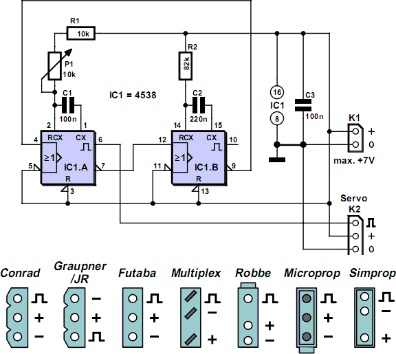
Servo Tester Using A 4538

There are times when a small servo tester for modelling comes in very useful. Everybody who regularly works with servos will know several instances when such a servo tester will come in handy. The function of a servo tester is to generate a pulsing signal where the width of the positive pulse can be varied between 1 and 2 ms. This pulse-width determines the position the servo should move to. The signal has to repeat itself continuously, with a frequency of about 40 to 60 Hz. These circuits often use an NE555 or one of its derivatives to generate the pulses. This time we have used a 4538 for variety. This IC contains two astable multi-vibrators. You can see from the circuit diagram that not many other components are required besides the 4538. The astable multi-vibrator in a 4538 can be started in two ways. When input I 0 (pin 5 or 11) is high, a rising edge on input I 1 (pin 4 or 12) is the start signal to generate a pulse.

The pulse-width at the output of IC1a is equal to (R1+P1)×C1. This means that when potentiometer P1 is turned to its minimum resistance, the pulse-width will be 10 k × 100 n = 1 ms. When P1 is set to maximum (10 k), the pulse-width becomes 20 k × 100 n = 2 ms. At the end of this pulse inverting output Q generates a rising edge. This edge triggers IC1.B, which then generates a pulse. The pulse-width here is 82 k × 220 n ˜ 18 ms. At the end of this pulse the Q output will also generate a rising edge. This in turn makes IC1.A generate a pulse again. This completes the circle. Depending on P1, the total period is between 19 and 20 ms. This corresponds to a frequency of about 50 to 53 Hz and is therefore well within the permitted frequency range.

Infra-Red Remote Control Tester

This little circuit is invaluable for quick go/no-go testing of just about any remote control transmitting infra-red (IR) light. The tester is battery-powered, built from just a handful of commonly available and inexpensive parts, and fits in a compact enclosure. Schmitt trigger gate IC1f is used as a quasi-analogue amplifier with, unusually, an infra-red emitting diode (IRED) type LD274 acting as the sensor element. An R-C network, C1-R2, is used at the output of the gate because all IR remote controls transmit pulse bursts, and to prevent the output LED, D2, lighting constantly when day-light or another continuous source of IR light is detected.


This creates a useful ‘quick test’ option: point the tester at direct daylight, and the indicator LED should light briefly. The sensitivity of the tester is such that IR light from remote control is detected at a distance of up to 50 cm. The circuit is designed for very low power consumption, drawing less than 1 mA from the battery when IR light is detected, and practically no current when no light is detected. Hence no on/off switch is required. The construction drawing shows how the tester may be ‘cased’ using a small ABS case from Conrad.

COMPONENTS LIST
Resistors:
R1,R2 = 10MW
Capacitor:
C1 = 10nF
Semiconductors:
D1 = LD274 (Siemens)
D2 = LED, 3mm, low-current
IC1 = 74HC14
Miscellaneous:
Bt1 = 3V Lithium cell with solder tags, e.g.type CR2045 (560 mAh)