Tampilkan postingan dengan label Charger. Tampilkan semua postingan

Kamis, 10 Januari 2013

Li-Ion Battery Charger

The LP2951 regulator is manufactured by National Semiconductors. The choice of values is from an application note "Battery Charging", written by Chester Simpson. Diode D1 can be any diode from the 1N00x series, whichever is conveniently available. It functions as a blocking diode, to prevent a back flow of current from the battery into the LP2951 when the input voltage is disconnected. Charging current is about 100+mA, which is the internally-limited maximum current of the LP2951. For those wondering, this is compatible with just about any single-cell li-ion battery since li-ion can generally accept a charging current of up to about 1c (i.e. charging current in mA equivalent to their capacity in mAh, so a 1100mAh li-ion cell can be charged at up to 1100mA and so on).


 A lower charging current just brings about a correspondingly longer charge time. IMHO 100mA is quite low, low enough that the circuit can be used for an overnight charger for many typical single-cell li-ion batteries. The resistors are deliberately kept at large orders of magnitude (tens/hundred Kohm and Mohm range) to keep the off-state current as low as possible, at about 2?A. Resistor tolerances should be kept at 1% for output voltage accuracy. The 50k pot allows for an output voltage range between 4.08V to 4.26V - thus allowing calibration as well as a choice between a charging voltage of 4.1V or 4.2V depending on the cell to be charged. The capacitors are for stability, especially C2 which prevents the output from ringing/oscillating.

Parts List

IC1 = LP2951, voltage regulator
D1 = 1N4002, General purpose diode
R1 = 2M, 1%, metal-film
R2 = 806K, 1%, metal-film
P1 = 50K, potentiometer
C1 = 0.1uF, polyester
C2 = 2.2uF/16V, electrolytic
C3 = 330pF, ceramic

Lead Acid Battery Charger #1

Except for use as a normal Battery Charger, this circuit is perfect to 'constant-charge' a 12-Volt Lead-Acid Battery, like the one in your flight box, and keep it in optimum charged condition. This circuit is not recommended for GEL-TYPE batteries since it draws to much current. The above circuit is a precision voltage source, and contains a temperature sensor with a negative temperature coλficient. Meaning, whenever the surrounding or battery temperature increases the voltage will automatically decrease. Temperature coλficient for this circuit is -8mV per °Celcius. A normal transistor (Q1) is used as a temperature sensor. This Battery Charger is centered around the LM350 integrated, 3-amp, adjustable stabilizer IC. Output voltage can be adjusted with P1 between 13.5 and 14.5 volt.


T2 was added to prevent battery discharge via R1 if no power present. P1 can adjust the output voltage between 13.5 and 14.5 volts. R4's value can be adjusted to accommodate a bit larger or smaller window. D1 is a large power-diode, 100V PRV @ 3 amp. Bigger is best but I don't recommend going smaller. The LM350's 'adjust' pin will try to keep the voltage drop between its pin and the output pin at a constant value of 1.25V. So there is a constant current flow through R1. Q1 act here as a temperature sensor with the help of components P1/R3/R4 who more or less control the base of Q1. Since the emitter/base connection of Q1, just like any other semiconductor, contains a temperature coλficient of -2mV/°C, the output voltage will also show a negative temperature coλficient.

That one is only a factor of 4 larger, because of the variation of the emitter/basis of Q1 multiplied by the division factor of P1/R3/R4. Which results in approximately -8mV/°C. To prevent that sensor Q1 is warmed up by its own current draw, I recommend adding a cooling rib of sorts. (If you wish to compensate for the battery-temperature itself, then Q1 should be mounted as close on the battery as possible) The red led (D2) indicates the presence of input power.Depending on what type of transistor you use for Q1, the pads on the circuit board may not fit exactly (in case of the BD140).


Lead Acid Battery Charger #2

The above pictured schematic diagram is just a standard constant current model with a added current limiter, consisting of Q1, R1, and R4. The moment too much current is flowing biases Q1 and drops the output voltage. The output voltage is: 1.2 x (P1+R2+R3)/R3 volt. Current limiting kicks in when the current is about 0.6/R1 amp. For a 6-volt battery which requires fast-charging, the charge voltage is 3 x 2.45 = 7.35 V. (3 cells at 2.45v per cell). So the total value for R2 + P1 is then about 585 ohm. For a 12 V battery the value for R2 + P1 is then about 1290 ohm. For this power supply to work efficiently, the input voltage has to be a minimum of 3V higher than the output voltage. P1 is a standard trimmer potentiometer of sufficient watt for your application. The LM317 must be cooled on a sufficient (large) coolrib. Q1 (BC140) can be replaced with a NTE128 or the older ECG128 (same company). Except as a charger, this circuit can also be used as a regular power supply.


 Parts List:

R1 = 0.56 Ohm, 5W, WW
R2 = 470 Ohm C2 = 220nF
R3 = 120 Ohm
R4 = 100 Ohm
C1 = 1000uF/63V
Q1 = BC140
Q2 = LM317, Adj. Volt Reg.
C3 = 220nF (On large coolrib!)
P1 = 220 Ohm


Micropower Battery Protector

Protect your expensive batteries from discharge damage with this mini-sized electronic cutout switch. It uses virtually no power and can be built to suit a wide range of battery voltages.

Main Features
  • Disconnects load at preset battery voltage
  • Automatically reconnects load when battery recharged
  • Ultra-low power consumption (<20ma)
  • Miniature size
  • 10A maximum rating
  • Suitable for use with 4.8-12.5V batteries
  • Transient voltage protection (optional)
Suitable for use in...
  • Cars, boats & caravans
  • Security systems
  • Emergency lighting
  • Small solar installations
  • Camera battery packs
  • Many other low-power applications
Picture of the project:


Back in May 2002, we (Silicon Chip) presented the "Battery Guardian", a project designed specifically for protecting 12V car batteries from over-discharge. This unit has proven to be very popular and is still available from kit suppliers. This new design does not supersede the Battery Guardian – at least not when it comes to 12V car batteries. Instead, it’s a more flexible alternative that can be used with a wide range of battery voltages.


In this new "Micropower Battery Protector", we’ve dispensed with the low-battery warning circuitry and the relatively cheap N-channel MOSFET used in the Battery Guardian in favour of a physically smaller module that steals much less battery power. It costs a little more but can switch lower voltages, allowing it to be used with 6V & 12V lead-acid batteries and 4-cell to 10-cell NiCd and NiMH battery packs.

PCB layout:


Most battery-powered equipment provides no mechanism for disconnecting the batteries when they’re exhausted. Even when the voltage drops too low for normal operation, battery drain usually continues until all available energy is expended. This is particularly true of equipment designed to be powered from alkaline or carbon cells but retro-fitted with rechargeables.

Circuit diagram:


Nicad Charger Uses Voltage Cut-Out

This circuit charges two NiCad cells with a constant current and features dual charging rates, voltage cutoff and an audible alarm. The circuit is powered by a 12VAC centre-tapped mains transformer, together with two rectifier diodes (D1 & D2) and a 1000mF filter capacitor. A 7806 3-terminal regulator is used to generate a 6V rail for the remainder of the circuit. Transistor Q1 and LED1 constitute a basic constant-current source. The forward voltage of the red LED (about 1.5V) minus Q1’s base-emitter voltage (about 0.6V) appears across the 6.8W or 15W emitter resistors, depending on the position of S1. With a 15W resistance in the emitter circuit, the charging current is about 60mA, whereas with 6.8W it is about 130mA.

This is sufficient to charge 600mAH "AA" cells in 14 hours and five hours, respectively. An LM393 voltage comparator (IC1) is used for the voltage cutoff function. Its inverting input is set to 2.9V (nominal) via trimpot VR1, while the non-inverting input senses battery voltage. This means that while the cells are being charged, the output transistor (in the LM393) is switched on, also switching on Q1 and enabling the current source. Once the cells are charged to approximately 80% or more of capacity, their terminal voltages will exceed 1.45V, so the voltage at the non-inverting input (pin 3) of IC1 will exceed the reference voltage on the inverting input (pin 2).


 This causes IC1’s output to switch off, in turn switching Q1 off and disabling the current source. To prevent rapid switching action around the voltage cutoff point, a 100nF capacitor provides feedback between the output and inverting input of the comparator. Four NAND gates are used to build two simple oscillators of different frequencies. When cascaded together, the result is a pulsed tone from the piezo transducer to indicate charge completion.

Editors note:
Absolute terminal voltage is not always a reliable indicator of Nicad battery charge state. Importantly, batteries should never be charged for longer than the manufacturer’s specified period.

Battery Charger Regulator

Most off-the-shelf car battery chargers cannot not be left connected to the battery for long periods of time as over-charging and consequent battery damage will occur. This add-on circuit is placed in series with the battery being charged and is powered by the battery itself. In effect, the circuit uses a high-current Mosfet to control the charging current and it turns off when the battery voltage reaches a preset threshold. Power for the circuit is fed from the battery to 3-terminal regulator REG1 which provides 8V.

LED1 indicates that the battery is connected and that power is available. The 555 timer IC is configured as an astable oscillator running at approximately 100kHz. It feeds a diode pump (D1 & D2) to generate adequate gate voltage for Mosfet Q3, enabling it to turn on with very little on resistance (typically 14 milliohms). With the Mosfet turned on, current flows from the charger's positive terminal so that charging can proceed. The battery voltage is monitored by 10kO pot VR1.


When the wiper voltage exceeds the conduction voltage of zener diode ZD1, transistor Q1 turns on and pulls pin 4 (reset) low to switch off the 555 and remove gate drive to the Mosfet. This process is progressive so that the cycle rapidly repeats itself as the battery charges. Eventually, a point is reached when the battery approaches its charged condition and the cycle slows right down. Transistor Q2 and LED2 function as a cycle indicator. When the battery is under charge, LED2 appears to be constantly on. When the battery is fully charged, LED2 briefly flicks off (charging) and returns to the on state (not charging) for a longer period.

Kamis, 03 Januari 2013

In-Car Charger And Switcher Circuit For SLA Battery

This circuit was devised to switch power to a Peltier cooler in a vehicle. Power to the load from the vehicle’s battery is switched by a SPDT relay while the ignition switch is turned on and from the SLA auxiliary battery when the ignition is off.

The SLA battery is charged from the vehicle’s battery. When the engine is running, the voltage remains fairly constant, which greatly simplifies the charging circuit. If the SLA battery is fully charged, any further charging current from the vehicle battery is limited by a 3.3W 5W resistor (R1). If the SLA battery is deeply discharged, the voltage drop across this resistor will be enough to bias on PNP transistor Q1. This will turn on P-channel Mosfet Q2 and it will provide further charging current via R2, effectively becoming a 2-step charger.

Since the paralleled resistors (R1 & R2) have a lower combined voltage drop, Q1 will receive lower base bias, which in turn will cause Mosfet Q2 to fully saturate. This positive feedback creates a clean transition between the two states and prevents Q2 from over-dissipating by being partially on. The current then will ramp down until the battery is only receiving a trickle charge and the voltage drop across the paralleled resistors is only a few dozen millivolts. Schottky diode D1 prevents the SLA battery from discharging into the vehicle’s accessory circuits when the engine is off.

Two safety devices are included in the circuit, the first being in-line fuse F1 which will prevent serious damage in case of shorts. In addition, a PTC resettable thermistor (RT1) protects the battery from sustained over-currents during the charging phase. It is a 1.85A hold, 3.70A trip device at 23°C. Since it has a positive temperature coefficient, at 70°C, these ratings decrease to 1A and 2A for hold and trip respectively, which can further protect the battery.
 

Lastly, to protect the SLA battery from deep discharge, a low voltage disconnect is included. This is centred around REG1, a voltage reference configured as a comparator. Its reference (REF) input is connected to a voltage divider, as long as "enable" switch S1 is closed.

Whenever the voltage at REG1’s reference terminal exceeds 2.5V, its anode will be pulled low, biasing on PNP transistor Q3. Q3 provides positive feedback via the 270kΩ resistor and diode D2 to turn on N-channel Mosfet Q4, which allows the load to be powered up.

If the SLA battery voltage drops below 10V, the reference terminal will fall below 2.5V and the anode of REG1 will go high, thereby removing bias from Q3 and turning off Q4 to disconnect the load and prevent deep discharge. LED1 indicates when power is being applied to the load.

NiCd Battery Charger With Reverse Polarity Protection

This NiCd battery Charger can charge up to 7 NiCd batteries connected in series. This number can be increased if the power supply is increased with 1.65V for each supplementary battery. If Q2 is mounted on a proper heatsink, the input voltage can be increased at a maximum of 25V. Unlike most of comercial NiCd chargers available on the market, this charger has a reverse polarity protection. Another great quality is that it does not discharge the battery if the charger is disconnected from the power supply.

Usually , NiCd batteries must be charged in 14 hours at a charging current equal with a tenth percent from battery capacity. For example, a 500 mAh is charged at 50 mA for 14 hours. If the charging current is too high this will damage the battery. The level of charging current is controlled with P1 between 0 mA – 1000 mA. Q1 is opened when the NiCd battery is connected with the right polarity or if the output terminals are empty. Q2 must be mounted on a heatsink. If you cannot obtain a BD679, then replace it with any NPN medium power Darlington transistor having the output parameters at 30V and 2A. By lowering R3 value the maximum output current can be increased up to 1A.

Parts:

P1 = 1K
R1 = 680R
R2 = 47K
R3 = 1R-3W
Q1 = BC557
Q2 = BD679 (Darlington)
D1-D5 = 1N4148
D6 = 1N4001

NiMh and NiCd Battery Charger Circuit

This automatic NiCd charger for 9V NiCd batteries is using 555 timer properties and is very easy to build. Why is an automatic 9 volts NiCd battery charger? Because you can leave the battery for charging as much as you like: it will be always completely charged and ready for use when is needed. It wont be overcharged and it will not discharge. With the values presented in the circuit diagram, the battery charger NiCd circuit is suitable for 6V and 9V batteries.

9 volt types with 6 and 7 cells are charging with 20mA; P1 must be adjusted so that the NiCd charger disconnects after 14 hours. Window inferior level is set at 1V below this value with P2. 5V battery type with 4 or 5 cells are charged at 55mA. Again, with P1 adjust the NiCd charger circuit so it disconnects after 14 hours. Window inferior level must be set at 0.8V below this value.


Parts:

P1 = 50K
P2 = 50K
R1 = 820R
R2 = 820R
R3 = 1K
R4 = 10K
R5 = 10K
R6 = 100R
D1 = 4.7V Zener
D2 = 1N4001
D4 = 1N4148
D5 = B40C1500 Diode Bridge
C1 = 220uF - 25V
Q1 = BC547B
IC = 555
B1 = 9V Ni-Cad Battery

A Friendly Charger Schematic for Mobile Phones

Most mobile chargers do not have current/voltage regulation or short-circuit protection. These chargers provide raw 6-12V DC for charging the battery pack. Most of the mobile phone battery packs have a rating of 3.6V, 650mAh. For increasing the life of the battery, slow charging at low current is advisable. Six to ten hours of charging at 150-200mA current is a suitable option. This will prevent heating up of the battery and extend its life


Parts:

Resistors:

P1 = 10K LOG
R1 = 1K
R2 = 1K
R3 = 1K
R4 = 1K
R5 = 3.3K
R6 = 16R/2W
R7 = 220R
R8 = 3.3R
R9 = 1K

Capacitors:

C1 = 470uF/25V
C2 = 10uF/25V
C3 = 1KuF/25V

Semiconductors:

D1 = Red LED
D2 = Green LED
Q1 = BC547
Q2 = BD677
ZD1 = 12V/1W
ZD2 = 5.6V/1W
IC1 = CA3130


Description:

The circuit described here, provides around 180mA current at 5.6V and protects the mobile phone from unexpected voltage fluctuations that develop on the mains line. So the charger can be left ‘on’ over night to replenish the battery charge. The circuit protects the mobile phone as well as the charger by immediately disconnecting the output when it senses a voltage surge or a short circuit in the battery pack or connector. It can be called a ‘middle man’ between the existing charger and the mobile phone.

It has features like voltage and current regulation, over-current protection, and high- and low-voltage cut-off. An added specialty of the circuit is that it incorporates a short delay of ten seconds to switch on when mains resumes following a power failure. This protects the mobile phone from instant voltage spikes. When short-circuit occurs at the battery terminal, resistor R8 senses the over-current, allowing Q1 to conduct and light up D1. Glowing of D2 indicates the charging mode, while D1 indicates short-circuit or over-current status.

The value of resistor R8 is important to get the desired current level to operate the cut-off. With the given value of R8 (3.3 ohms), it is 350 mA. Charging current can also be changed by increasing or decreasing the value of R7 using the ‘I=V/R’ rule. Construct the circuit on a common PCB and house in a small plastic case. Connect the circuit between the output lines of the charger and the input pins of the mobile phone with correct polarity.

Rabu, 02 Januari 2013

Low Cost Universal Battery Charger Schematic

Here is the circuit diagram of a low cost universal charger for NiCD - NiMH batteries. This circuit is Ideal for car use. It has ability to transform a mains adapter in to a charger . This one can be used to charge cellular phone, toys, portables, video batteries, MP3 players, ... and has selectable charge current. An LED is located in circuit to indicate charging. Can be built on a general purpose PCB or a veroboard. I hope you really like it.
Parts:

R1 = 120R-0...5W
R2 = See Diagram
C1 = 220uF-35V
D1 = 1N4007
D2 = 3mm. LED
Q1 = BD135
J1 = DC Input Socket


Specifications:
  • Ideal for in car use.
  • LED charge indication.
  • Selectable charge current.
  • Charges Ni Cd or NiMH batteries.
  • Transforms a mains adapter into a charger.
  • Charge cellular phone, toys, portables, video batteries …


Features:
  • LED function indication.
  • Power supply polarity protected.
  • Supply current: same as charge current.
  • Supply voltage: from 6.5VDC to 21VDC (depending on used battery)
  • Charge current (±20%): 50mA, 100mA, 200mA, 300mA, 400mA. (selectable)


Determining the supply voltage:

This table indicates the minimum and maximum voltages to supply the charger. See supply voltage selection chart below.

Example:

To charge a 6V battery a minimum supply voltage of 12V is needed, the maximum voltage is then 15V.

Voltage selection:

 Voltage Selection Chart - Low Cost Universal Battery Charger Circuit Diagram For NiCD and NiMH
Voltage Selection Chart For Low Cost Universal Battery Charger


Determining the charge current:

Before building the circuit, you must determinate how much current will be used to charge the battery or battery pack. It is advisable to charge the battery with a current that is 10 times smaller then the battery capacity, and to charge it for about 15 hours. If you double the charge current , then you can charge the battery in half the time. Charge current selection chart is located in diagram.

Example:

A battery pack of 6V / 1000mAh can be charged with 100mA during 15 hours. If you want to charge faster, then a charge current of 200mA can be used for about 7 hours.


Caution:

The higher charge current, the more critical the charge time must be checked. When faster charging is used, it is advisable to discharge the battery completely before charging. Using a charge current of 1/10 of the capacity will expand the lifetime of the battery. The charge time can easily be doubled without damaging the battery.

Mobile Phone and iPod Battery Charger

Using the USB port on your computer to charge your player’s batteries is not always practical. What if you do not have a computer available at the time or if you do not want to power up a computer just for charging? Or what if you are traveling? Chargers for Mobile Phones iPods and MP3 players are available but they are expensive and you need separate models for charging at home and in the car.

This charger can be used virtually anywhere. While we call the unit a charger, it really is nothing more than a 5V supply that has a USB outlet. The actual charging circuit is incorporated within the iPOD or MP3 player itself, which only requires a 5V supply. As well as charging, this supply can run USB-powered accessories such as reading lights, fans and chargers, particularly for mobile phones.

The supply is housed in a small plastic case with a DC input socket at one end and a USB type "A" outlet at the other end, for connecting to Mobile Phone, an iPod or MP3 player when charging. A LED shows when power is available at the USB socket. Maximum current output is 660mA, more than adequate to run any USB-powered accessory.


Parts:

P1 = 1K
R1 = 1R-0.5W
R2 = 1R-0.5W
R3 = 1R-0.5W
R4 = 1K
R5 = 560R
R6 = 10R-0.5W
R7 = 470R
C1 = 470uF-25V
C2 = 100nF-63V
C3 = 470pF
C4 = 100uF-25V
D1 = 1N5404
D2 = 1N4001
D3 = 1N5819
D4 = 5.1V-1W Zener Diode
D5 = 5mm. Red LED
L1 = 220uH
S1 = USB 'A' Type Socket
SW1 = On/Off Switch
IC1 = MC34063A


Specifications:

Output voltage ----------------------5V
Output current ---------------------660mA maximum for 5V out
Input voltage range ------------------9.5V to 15V DC
Input current requirement ----------500mA for 9V in, 350mA for >12V input
Input current with output shorted--- 120mA at 9V in, 80mA at 15V in
Output ripple ------------------------14mV (from no load to 660mA)
Load regulation ----------------------25mV (from no load to 660mA)
Line regulation ----------------------20mV change at full load from 9 to 18V input
No load input current ----------------20mA

(The specification for the computer USB 2.0 port requires the USB port to deliver up to 500mA at an output voltage between 5.25V and 4.375V).


The circuit is based around an MC34063 switch mode regulator. This has high efficiency so that there is very little heat produced inside the box, even when delivering its maximum output current. The circuit is more complicated than if we used a 7805 3-terminal regulator but since the input voltage could be 15V DC or more, the voltage dissipation in such a regulator could be 5W or more at 500mA. and 5W is far too much for a 7805, even with quite a large heatsink. Credit for this circuit goes to SiliconChip, A wonderful electronics magazine.

Dry Cell Battery Charger Using LM741

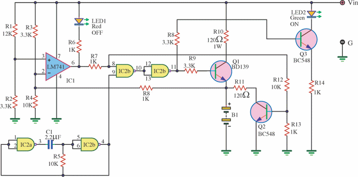
This is Dry Cell Battery Charger Circuit. That can use charger battery get that about 12 hour. When apply to power supply 9 volt the equipment that fix in the circuit use for size battery AA. If use the size C or D should devalue of Resistor RX down be 68ohm and should not lead battery come to serial while voltage in cell battery lower 1.6V. The Comparator Circuit with (IC741) control Gate output from Pulse Oscillator at use the integrated circuit CMOS 4011 change Transistor that do infront charger battery until voltage tall 1.6V Comparator Circuit more make LED Flasher warn know for protect Charger battery expire. The next time is if friends have Dry Cell Battery that use be finished already , don’t abandon , try apply new again yes.


Minggu, 18 November 2012

2 Cell Lithium Ion Charger


This circuit was build to charge a couple series Lithium cells (3.6 volts each, 1 Amp Hour capacity) installed in a portable transistor radio. 

The charger operates by supplying a short current pulse through a series resistor and then monitoring the battery voltage to determine if another pulse is required. The current can be adjusted by changing the series resistor or adjusting the input voltage. When the battery is low, the current pulses are spaced close together so that a somewhat constant current is present. As the batteries reach full charge, the pulses are spaced farther apart and the full charge condition is indicated by the LED blinking at a slower rate. 

A TL431, band gap voltage reference (2.5 volts) is used on pin 6 of the comparator so the comparator output will switch low, triggering the 555 timer when the voltage at pin 7 is less than 2.5 volts. The 555 output turns on the 2 transistors and the batteries charge for about 30 milliseconds. When the charge pulse ends, the battery voltage is measured and divided down by the combination 20K, 8.2K and 620 ohm resistors so when the battery voltage reaches 8.2 volts, the input at pin 7 of the comparator will rise slightly above 2.5 volts and the circuit will stop charging. 

The circuit could be used to charge other types of batteries such as Ni-Cad, NiMh or lead acid, but the shut-off voltage will need to be adjusted by changing the 8.2K and 620 ohm resistors so that the input to the comparator remains at 2.5 volts when the terminal battery voltage is reached. 

For example, to charge a 6 volt lead acid battery to a limit of 7 volts, the current through the 20K resistor will be (7-2.5)/ 20K = 225 microamps. This means the combination of the other 2 resistors (8.2K and 620) must be R=E/I = 2.5/ 225 uA = 11,111 ohms. But this is not a standard value, so you could use a 10K in series with a 1.1K, or some other values that total 11.11K