Tampilkan postingan dengan label Rumah Tangga. Tampilkan semua postingan

Jumat, 11 Januari 2013

Simple 6-Input Alarm

This simple alarm circuit was designed for use in a combined garage and rumpus room. It can be assembled on Veroboard and uses just one IC plus a handful of cheap components. The circuit is based on a straightforward 555 timer circuit (IC1). This is wired as a monostable and sets the siren period which is adjustable up to about three minutes using potentiometer VR1. In operation, IC1's pin 2 input monitors the detector circuit for negative-going signals. When a switch is closed, a brief negative-going pulse is applied to pin 2 via a 10µF capacitor and its corresponding series diode (D2-D7). This triggers IC1 which switches its pin 3 output high and switches off relay RLY1 (ie, RLY1 is normally on).


 As a result, the piezo siren sounds for the duration of the monostable period. In addition, relay RLY2 is turned on via diode D9 and latches on via D10. This means that the strobe light (which is wired to the normally open contact) will continue to flash until the alarm is switched off (via the keyswitch). At the end of the monostable period, RLY1 turns off and this turns off the piezo siren. The circuit can then be retriggered by any further trigger inputs from the switches. A variety of detectors with normally open contacts can be used for the switches, including reed switches, pressure mats, IR detectors and glass breakage detectors. All switches must be open before the alarm is switched on.

Infrared Proximity Detector Alarm

This circuit can be built from readily available low-cost components, some of which may even be hiding in your junkbox! The indicated value of 22 Ω for resistor R1 causes an average current of about 65 mA through infrared emitter D1. Because the IRED is pulsed at a duty factor of about 50% through the action of T1 and IC1, a peak current of 128 mA flows during every half cycle. This may seem a lot but in fact is well within the safe specification of the LD274. The LM567 PLL IC is configured to supply a switching frequency of about 20 kHz. When the infrared beam emitted by D1 is reflected by a nearby object, IC1, through receiver diode D2 and transistor T2, receives the recovered 20 kHz signal at its input, pin 3.


Because the ‘567 PLL is then locked, the IC output (pin 8), drops low, triggering the 555 chip in monostable mode (IC2) and so causing acoustic actuator Bz1 to sound. The monostable remains on as long as the reflected signal is being received. Because of the presence of T3, capacitor C5 is allowed to charge only when no signal is being received. In that condition, the 555 is turned off automatically after a time determined by R9-C5. Using the component values shown, this will be about 5 seconds. Obviously D1 and D2 should be mounted such that the latter can only pick up reflected infrared light.

The choice of the two infrared components used in this circuit will be uncritical but they must be ‘band’ compatible, i.e., generate (D1) and respond to (D2) the same wavelength. The operating point of the receiver input circuit is rather dependent on ambient day-light levels and the value of R4 may need to be adjusted a little to ensure a voltage of between 1.5 V and 4 V on the collector of T1 when no signal is being received. Some dc buzzers cause a lot of back-emf so it may be necessary to insert a diode in series with the output of IC1. If necessary, this diode should preferably be a Schottky type because of the inherent low voltage drop of about 0.4 V as opposed to 0.65 V for a typical small-signal silicon diode.

Rabu, 26 Desember 2012

Automatic Water Tank Filler Circuit Diagram

This circuit has been very useful in filling a header tank for a reticulated water supply on a farm. Eight troughs are supplied in different paddocks where a lack of water would have serious consequences for the stock. In the past, the tank had been filled daily by a time clock which was not successful. During hot weather, the stock would empty the tank on a regular basis and then be without water for several hours or the tank would overflow and flood the area if the weather was wet and the cattle did not drink much.


The circuit described has been used to maintain the level of water in the header tank within prescribed limits. It controls a 3HP submersible bore pump which has a high starting current, necessitating a solid-state relay sufficient to take the starting load. Two Darlington transistors, Q1 & Q3, in conjunction with Q2 & Q4, are connected to the upper and lower water sensors in the tank. Q2 & Q4 have a common 5.6kO load resistor and function as a NOR gate. The output of the NOR gate drives Q5 which activates relay RLY1.

Initially, when the water level is low, both sensors will be open-circuit, the NOR gate output will be high and the relay will be turned on. This causes the normally closed (NC) contacts of the relay to open and disconnect the lower sensor. However, the upper sensor will still be open circuit and the NOR gate output will be high, keeping the relay closed. The normally open (NO) contact of the relay will be closed to operate the solid-state relay RLY2 to run the pump.

This state continues until the water reaches the top sensor which will then drop the output from the NOR gate to 0V. The disables relay RLY1 and the pump is stopped. In practice the upper level sensor is just below the overflow from the tank and the lower sensor about half way up the tank. The sensor contacts are simply two stainless steel screws about 25mm apart and screwed through the poly tank walls. The wiring junctions on the side of the tank are protected by neutral-cure silicone sealant.

Mosquito Repeller " pengusir Nyamuk "

With the return of the fine weather, you’ll doubtless be enjoying lazing around of an evening on your patio or in your garden, but even if you’re not surrounded by marshes or other shallow water it’s very likely some intruding mosquitoes will come along to spoil this idyllic scene. Although indoors it’s easy to get rid of them these days, indeed even to prevent them coming into the house, the same can’t be said for the great outdoors. We might mention the well-known Chinese coils – the only thing Chinese about them is undoubtedly their name – which very often drive people away as much as mosquitoes, if not more! Moreover they are nasty things to handle.

There are also UV (ultra-violet) ‘electrocutors’ consisting of a blue lamp surrounded by two closely-spaced grilles between which a high voltage is applied. The mosquitoes (and fies and other flying insects) are supposedly attracted by the color of the lamp and as they approach, get electrocuted in contact with the two grilles. The only thing you have to do is pull out the drawer from time to time and get rid of the mass of dead insects. Even though the effectiveness of these first two products remains questionable, it is less so than the one we’re nonetheless going to describe here.

We’re talking about an ultrasonic mosquito repellent. The principle, as described by its numerous promoters, is as follows. Only the female mosquitoes bite (that at least is an undisputed scientific fact) and they bite when they need to feed, and above all, to feed their eggs. In this situation, they seek to avoid the males whose ‘job’ has already been done, and so they fy away from the frequencies emitted by the males when they are on heat. This is where opinions now diverge.

According to certain publications, the frequency emitted by the male mosquitoes is said to be around 20–25 kHz, and so within the realm of ultrasound. But according to others, it is in the region of 5–7 kHz instead; frequencies that a human ear, even an elderly one, can still hear very well. Rather than spending lots of money (of the order of tens of pounds) buying such a device, which moreover generally have a fixed frequency, we’re suggesting building one yourself so that you can carry out your own research this summer, especially since the circuit proposed is very simple and cheap to build.

As the figure shows, it uses just a single IC, a CMOS type 4047. This very multi-purpose IC can be wired in very many operating modes, including that of the multivibrator or astable used here. The operating frequency is set by the external components C1, R1, and P1; the latter makes it possible to slightly adjust the frequency, given the uncertainty that exists over the most efective value…To best reproduce the high frequencies produced by the generator, the output transducer used is a simple tweeter, but it must be a piezo one. Such a tweeter behaves in fact much like a capacitor, and so doesn’t overload the CMOS IC outputs that are incapable of supplying a substantial current, as everyone knows who’s ever worked with 400 series CMOS logic.

To obtain an output signal of sufficient amplitude while being powered from a single 9 V battery, this tweeter is connected between the 4047’s Q and Q outputs, making it possible to apply complementary (antiphase) signals to the tweeter so it ‘sees’ an alternating voltage of double the supply voltage. In purely theoretical terms, this quadruples the output power available. In practice, it’s better to regard it as tripling it, but the beneft achieved by doing it this way is nonetheless very real. All that remains is for you to place the project in the middle of the patio table or beside your lounger in order to get a taste of the calm of a summer’s evening without mosquitoes bothering you acoustically or worse, biting. At any rate, that’s what we wish for you…

Minggu, 16 Desember 2012

Remote Operated Home Appliances Circuit

Here is the circuit diagram of Remote Operated Home Appliances or Remote controlled Home appliances. Connect this circuit to any of your home appliances (lamp, fan, radio, etc) to make the appliance turn on/off from a TV, VCD, VCR, Air Conditioner or DVD remote control. The circuit can be activated from up to 10 meters. It is very easy to build and can be assembled on a veroboard or a general-purpose PCB.


Parts:

R1 = 220K
R2 = 330R
R3 = 1K
R4 = 330R
R5 = 47R
C1 = 100uF-16V
C2 = 100nF-63V
C3 = 470uF-16V
D1 = 1N4007
D2 = Red LED
D3 = Green LED
Q1 = BC558
Q2 = BC548
IR = TSOP1738
IC1 = CD4017
RL1 = Relay 5V DC


Circuit Operation:

The 38kHz infrared rays generated by the remote control are received by IR receiver module TSOP1738 of the circuit. Pin 1 of TSOP1738 is connected to ground, pin 2 is connected to the power supply through R5 and the output is taken from pin 3. The output signal is amplified by Q1. The amplified signal is fed to clock pin 14 of decade counter IC CD4017 (IC1). Pin 8 of IC1 is grounded, pin 16 is connected to vcc and pin 3 is connected to D2 (Red LED), which glows to indicate that the appliance is ‘off.’

The output of IC1 is taken from its pin 2. D3 connected to pin 2 is used to indicate the ‘on’ state of the appliance. Q2 connected to pin 2 of IC1 drives relay RL1. D1 acts as a freewheeling diode. The appliance to be controlled is connected between the pole of the relay and neutral terminal of mains. It gets connected to live terminal of AC mains via normally opened (N/O) contact when the relay energizes. If you want to operate a DC 12 volt relay then use a regulated DC 12 volt power supply for DC 12 volt Relay and remember that the circuit voltage not be exceeded more than DC 5 volts

Kamis, 13 Desember 2012

IC Controlled Emergency Light With Charger Circuit

Here is the circuit diagram of IC Controlled Emergancy Light With Charger or simply 12V to 220V AC inverter circuit. The circuit shown here is that of the IC controlled emergency light. Its main features are: automatic switching-on of the light on mains failure and battery charger with over-charge protection. When mains is absent, relay RL2 is in de-energized state, feeding battery supply to inverter section via its N/C contacts and switch S1.

The inverter section comprises IC2 (NE555) which is used in stable mode to produce sharp pulses at the rate of 50 Hz for driving the MOSFETs. The output of IC2 is fed to gate of MOSFET (Q4) directly while it is applied to MOSFET (Q3) gate after inversion by transistor Q2. Thus the power amplifier built around MOSFETs Q3 and Q4 functions in push-pull mode. The output across secondary of transformer T2 can easily drive a 230-volt, 20-watt fluorescent tube. In case light is not required to be on during mains failure, simply flip switch S1 to off position. Battery overcharge preventer circuit is built around IC1 (LM308).

Its non-inverting pin is held at a reference voltage of approximately 6.9 volts which is obtained using diode D5 (1N4148) and 6.2-volt zener D6. The inverting pin of IC1 is connected to the positive terminal of battery. Thus when mains supply is present, IC1 comparator output is high, unless battery voltage exceeds 6.9 volts. So transistor Q1 is normally forward biased, which energises relay RL1. In this state the battery remains on charge via N/O contacts of relay RL1 and current limiting resistor R2. When battery voltage exceeds 6.9 volts (overcharged condition), IC1 output goes low and relay RL1 gets de-energised, and thus stops further charging of battery. MOSFETs Q and Q4 may be mounted on suitable heat sinks.

 Parts:

Resistors
R1 = 1K
R2 = 10R-1W
R3 = 820R
R4 = 1K
R5 = 10K
R6 = 1K
R7 = 100R
R8 = 1K

Capacitors
C1 = 1000uF-25V
C2 = 10uF-16V
C3 = 0.01uF

Diodes
D1 = 1N4007
D2 = 1N4007
D3 = 1N4007
D4 = 1N4007
D5 = 1N4148
D6 = 6.2V Zener
D7 = 1N4007
D8 = 1N4148

Transistors
Q1 = SL100
Q2 = 2N2222
Q3 = IRF840
Q4 = IRF840

Integrated Circuits
IC1 = LM308
IC2 = NE555

Miscellaneous
S1 = SPST Switch
B1 = 6V-4A Battery
B2 = 6V-4A Battery
TI = 220V AC Primary to 0V-6V 250mA Secondary Transformer
T2 = 4.5V-0V-4.5V 5A Primary To 230V AC Secondary Transformer

Fully Automatic Emergency Light

This simple automatic emergency light has the following advantages over conventional emergency lights:
  1. The charging circuit stops automatically when the battery is fully charged. So you can leave the emergency light connected to AC mains overnight without any fear.
  2. Emergency light automatically turns on when mains fails. So you don’t need a torch to locate it.
  3. When mains power is available, emergency light automatically turns off.
The circuit can be divided into inverter and charger sections. The inverter section is built around timer NE555, while the charger section is built around 3-terminal adjustable regulator LM317. In the inverter section, NE555 is wired as an astable multivibrator that produces a 15kHz squarewave. Output pin 3 of IC 555 is connected to the Darlington pair formed by transistors SL100 (T1) and 2N3055 (T2) via resistor R4.

The Darlington pair drives ferrite transformer X1 to light up the tubelight. For fabricating inverter transformer X1, use two EE ferrite cores (of 25×13×8mm size each) along with plastic former. Wind 10 turns of 22 SWG on primary and 500 turns of 34 SWG wire on secondary using some insulation between the primary and secondary. To connect the tube-light to ferrite transformer X1, first short both terminals of each side of the tube-light and then connect to the secondary of X1. (You can also use a Darlington pair of transistors BC547 and 2N6292 for a 6W tube-light with the same transformer.)
 
 
When mains power is available, reset pin 4 of IC 555 is grounded via transistor T4. Thus, IC1 (NE555) does not produce square-wave and emergency light turns off in the presence of mains supply. When mains fails, transistor T4 does not conduct and reset pin 4 gets positive supply though resistor R3. IC1(NE555) starts producing square wave and tube-light turns on via ferrite transformer X1. In the charger section, input AC mains is stepped down by transformer X2 to deliver 9V-0-9V AC at 500mA. Diodes D1 and D2 rectify the output of the transformer. Capacitors C3 and C4 act as filters to eliminate ripples.

The unregulated DC voltage is fed to IC LM317 (IC2). By adjusting preset VR1, the output voltage can be adjusted to deliver the charging voltage. When the battery gets charged above 6.8V, zener diode ZD1 conducts and regulator IC2 stops delivering the charging voltage. Assemble the circuit on a general-purpose PCB and enclose in a cabinet with enough space for the battery and switches. Connect a 230V AC power plug to feed charging voltage to the battery and make a 20W tube outlet in the cabinet to switch on the tube-light.

Automatic Light Dimmer

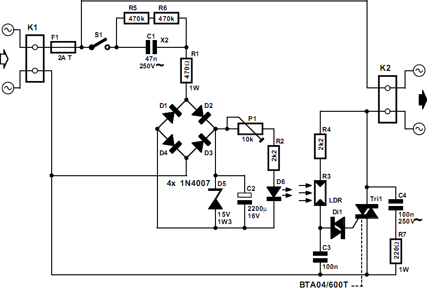
In many cases, the dimmer presented here may be built into a wall-mounted box containing the light switch. It is intended for use with 240 V incandescent lamps only. When it is fitted, and the light is switched on, the lamp does not come on fully for about 400 ms (which is not noticeable). When the light is switched off, it stays on unchanged for about 20 s, and then goes out gradually. This has the advantage that it is not immediately dark when the light is switched off. When light switch S1 is turned on, capacitor C2 is charged via R1, C1 and bridge rectifier D1–D4. Zener diode D5 limits the potential across C2 to about 15 V. After a short while, diode D6 lights, whereupon a potential difference ensues across light sensitive resistor R3, which is sufficient to trigger triac Tr1.


The light then comes on. When the light switch is turned off, C2 is discharged via P1, R2 and D6. When the potential across C2 drops, the brightness of the LED diminishes, so that the p.d. across R3 also drops. The increasing resistance of R3 effects phase angle control of the triac so that the light is dimmed gradually. The dimming time may be altered with P1 within the time range determined by network R2-C2. The circuit operates correctly only, of course, when the LDR is not exposed to light other than that from the LED. The type of LDR is not particularly important, as long as it is not too long: in the prototype, a model with a length of 5 mm was used

Vehicle Interior Lighting With Switch-Off Delay

Nowadays, a switch-off delay for the vehicle interior lighting is a naturally a standard feature. However, with certain models having only spartan fittings, or older-model vehicles, you’re left sitting in the dark as soon as you climb in and close the door. That calls for an aftermarket accessory! The author built this circuit using ‘normal’ components (with leads), but in the SMD manner, which means fitting the components on the copper side. The only holes drilled in the circuit board were the four fixing holes, and the entire assembly was firmly attached to the surface of the heatsink for power transistor T3 (the author used a finned heat sink rated at 7.2 °C/W). The heatsink is at ground potential.
A value of 1 Ω was used for R3 with satisfactory operation of the darlington. The light goes on when the door is opened. After the door is closed, it continues to illuminate the interior of the car at full brightness for around 30 seconds,after which it slowly dims. Approximately 1 minute after the door is closed, the quiescent current drops to zero.

Rabu, 12 Desember 2012

Reservoir Pump Controller

This circuit operates an automotive windscreen washer pump to fill a 20-litre drum from a 205-litre water reservoir. The drum is suspended above a drip line, which irrigates a vegetable garden. Two stainless steel probes mounted in the drum act as sensors for the system. One probe is positioned at the high water mark, the other at about half-full. The pump power is switched by a 12V automotive relay (RLY1). Two op amps (IC1a & IC1b) connected as voltage comparators form the basis of the circuit. Initially, assume a falling water level with the pump switched off. When the water level exposes the lower probe, the non-inverting input (pin 5) of IC1b rises to about 7.4V. With trimpot VR2 correctly adjusted, this will be higher than the voltage on pin 6.

The output (pin 7) therefore swings high, biasing Q1 into conduction. This in turn causes Q4 to conduct, switching on the relay and starting the pump. In addition, when Q4 switches on it supplies base current to Q3 via a 6.8kO resistor. Initially, this current flows through the 47µF capacitor, but once its base-emitter voltage reaches about 0.6V, Q3 conducts. This action latches Q4 in the "on" state, as its base current can flow to ground via Q3 when Q1 stops conducting – which will occur when the rising water level reaches the low probe. When the water level reaches the high probe, the voltage on the non-inverting input (pin 2) of IC1a decreases markedly due to the conductivity of the water.


If trimpot VR1 is correctly adjusted, the output (pin 1) swings high, switching on Q2. This discharges the 47µF capacitor and robs Q3 of its base current, switching this transistor off. This in turn switches off Q4 and the relay. The zener diodes and 1kO series resistors at the probe inputs protect the op amp’s high impedance inputs from the effects of static discharge. The 47µF capacitor in parallel with the base-emitter junction of Q1 prevents the latching function from being activated when power is applied to the circuit. The author’s setup is powered from an old car battery charged from a 12V solar panel.

Selasa, 11 Desember 2012

Water reservoir automatic level control, Simple circuitry - 12V supply

By means of a Relay, employed to drive a water pump, this circuit provides automatic level control of a water reservoir or well. The shorter steel rod is the "water high" sensor, whereas the longer is the "water low" sensor. When the water level is below both sensors, IC1C output (pin #10) is low; if the water becomes in contact with the longer sensor the output remains low until the shorter sensor is reached. At this point IC1C output goes high, Q1 conducts, the Relay is energized and the pump starts operating.

Now, the water level begins to decrease and the shorter sensor will be no longer in contact with the water, but IC1C output will be hold high by the signal return to pin #5 of IC1B, so the pump will continue its operation. But when the water level falls below the longer sensor, IC1C output goes low and the pump will stop. SW1 is optional and was added to provide reverse operation. Switching SW1 in order to connect R3 to pin #11 of IC1D, the pump will operate when the reservoir is nearly empty and will stop when the reservoir is full. In this case, the pump will be used to fill the reservoir and not to empty it as in the default operating mode.

 Parts:

R1 = 15K - 1/4W Resistors
R2 = 15K - 1/4W Resistors
R3 = 10K - 1/4W Resistor
R4 = 1K - 1/4W Resistor
D1 = LED - any type and color
D2 = 1N4148 - 75V 150mA Diode
Q1 = BC337 - 45V 800mA NPN Transistor
IC1 = 4001 Quad 2 Input NOR Gate CMos IC
SW = SPDT Toggle or Slide Switch (Optional)
RL1 = Relay with SPDT 2A @ 230V switch
Coil Voltage 12V - Coil resistance 200-300 Ohm
Two steel rods of appropriate length


Notes:
  • The two steel rods must be supported by a small insulated (wooden or plastic) board.
  • The circuit can be used also with non-metal tanks, provided a third steel rod having about the same height of the tank will be added and connected to the circuit's negative ground.

Selasa, 27 November 2012

Simple Electronic Code Lock

The circuit diagram of a simple electronic code lock is shown in figure. A 9-digit code number is used to operate the code lock.When power supply to the circuit is turned on, a positive pulse is applied to the RESET pin (pin 15) through capacitor C1. Thus, the first output terminal Q1 (pin 3) of the decade counter IC (CD 4017) will be high and all other outputs (Q2 to Q10) will be low. To shift the high state from Q1 to Q2, a positive pulse must be applied at the clock input terminal (pin 14) of IC1. This is possible only by pressing the push-to-on switch S1 momentarily.
Circuit diagram:


On pressing switch S1, the high state shifts from Q1 to Q2. Now, to change the high state from Q2 to Q3, apply another positive pulse at pin 14, which is possible only by pressing switch S2. Similarly, the high state can be shifted up to the tenth output (Q10) by pressing the switches S1 through S9 sequentially in that order. When Q10 (pin 11) is high, transistor T1 conducts and energises relay RL1. The relay can be used to switch ‘on’ power to any electrical appliance. Diodes D1 through D9 are provided to prevent damage/malfunctioning of the IC when two switches corresponding to ‘high’ and ‘low’ output terminals are pressed simultaneously.
Capacitor C2 and resistor R3 are provided to prevent noise during switching action. witch S10 is used to reset the circuit manually. Switches S1 to S10 can be mounted on a keyboard panel, and any number or letter can be used to mark them. Switch S10 is also placed together with other switches so that any stranger trying to operate the lock frequently presses the switch S10, thereby resetting the circuit many times. Thus, he is never able to turn the relay ‘on’. If necessary, two or three switches can be connected in parallel with S10 and placed on the key-board panel for more safety. A 12V power supply is used for the circuit. The circuit is very simple and can be easily assembled on a general-purpose PCB. The code number can be easily changed by changing the connections to switches (S1 to S9).

Electronic Code Lock

Nowadays, electronic code locks are usually based on microcontrollers. However, if you like your electronics discrete, you will enjoy the battery-operated circuit shown here. Since the circuit automatically switches off after the door has been opened and draws no current in the idle state, three alkaline batteries (mignon, AA or R6 cells) are good for around 5,000 door openings. The main advantage is that the door opener can also be powered from the battery, so it’s not necessary to run any extra cables.
 
Project  Image :
 
 
Figure 1 shows the schematic diagram of the circuit, which is split into two parts. The first part is the control panel, which consists of a 12-position keypad and two LEDs. The second part is the programming and evaluation logic, which contains only standard logic ICs. The control panel is connected to the logic board by a 16-way flat cable. The keypad circuit is laid out with separate connections to the individual switches, instead of a matrix. The code is programmed using the two pin connector strips K1 and K2.  The circuit allows any desired combination of numbers to be used for the code, up to a maximum of 9 positions. Press-ing a particular button, which in principle is random but which naturally must be specified in advance, awakens the circuit from the zero-current idle state. This Start button cannot be used in the subsequent code sequence. The Start button is programmed by connecting a wire bridge from the associated pin of K2 to pin 1 of K1.  The code sequence is programmed in a similar manner. The first numeral of the code is programmed by connect-ing the associated pin of K2 to pin 2 of K1, the connection for the second numeral is made to pin 3 of K1, the third to pin 4 and so on. Numerals that are not used in the code do not actually have to be connected. However, if the unused buttons are connected to VDD, the code lock will assume that an error has occurred if any of these buttons is pressed and will reset the circuit. Pressing the Start button switches on transistor T1, which connects the supply voltage source to the code lock. This is indicated by the yellow LED (D20).
 
Circuit diagram :
 
 
Part List :
Resistors :
R1,R2 = not fitted
R3 = 220kΩ
R4,R5 = 1MΩ
R6 = 220kΩ
R7,R9,R10,R17 = 100kΩ
R8,R12,R14 = 2MΩ2
R11 = 560Ω
R13,R15,R20 = 1kΩ5
R16 = 100kΩ
R18 = 120Ω
R19 = 10k
R21-R24 = 3Ω3
R25-R35 = 22kΩ
Capacitors :
C1,C6,C7,C8,C10 = 100nF
C2,C3,C5 = 10nF
C4 = 1µF
C9 = 330nF
C11 = 47µF 16V radial
Semiconductors :
D1-D9,D11,D13,D14,D15,D17,
D18 = 1N4148
D10,D12 = zener diode 1V2
0.4W*
D16 = 1N4001
D19 = LED, green
D20 = LED, yellow
T1 = BC327
T2,T3,T4 = BC337
T5 = BD140
IC1 = 4017
IC2,IC3 = 4069 or 40106
Miscellaneous :
JP1 = jumper
K1,K2 = 12-way pinheader or
wire links
K3,K4 = not required (ribbon
cable )
K5, K6 = 2-way PCB terminal
block, lead pitch 5mm
S1-S12 = pushbutton with
make contact
 
Since the logic ICs are now enabled, the output of IC3f will be High, so T2 also conducts and pulls the base of T1 to ground. This means that the Start button can be released without affecting the circuit. However, C11 can now slowly charge via the high resistance of R12 until the voltage at the inverter input is high enough to cause its output to go Low, which interrupts the supply voltage to the circuit and puts it back into the idle state. The valid code must therefore be entered during the time interval determined by this R–C time constant. Once the supply voltage is disconnected, C11 discharges rapidly via D18. This is important, since other-wise C11 could retain its charge for a long time. This would make the time allowed for entering the code significantly shorter the next time the lock is used.  Pressing the Start button also has other consequences. Via the Start switch, ground potential arrives at IC2d, where it causes a pulse to be generated that places counter IC1 in a defined state (Q0 = 1) prior to the entry of the first code numeral. The first code numeral can now be entered. If the correct button is pressed, the High potential from Q0 passes through the closed switch to reach IC2d–IC2a. This net-work generates a positive pulse at the instant that the but-ton is released. This pulse clocks the counter, so that the High level from Q0 moves by one position to Q1. This process repeats itself until all code numerals have been entered. 
 
  PCB Layout :
 
 
After the ninth numeral has been entered, the positive volt-age jumps to Q9, where it charges C4 (if jumper JP1 is installed). While C4 is charging, the output of IC2e goes Low for approximately two seconds, and the output of IC3d goes high for the same interval. Power transistor T5 is switched on via R19 and T4 to supply current to the door opener. At the same time, IC3a switches on the green LED (D19) to indicate that the door can be opened. T3 limits the current through the door opener to around 700 mA. Once C4 is sufficiently charged, the output of IC2e changes to High. Not only does this switch off the door opener, but the positive edge also generates a pulse in the network IC2f/IC3c that passes through D14 to reach IC1 as a reset pulse (D14, D17 D13 and R7 together form a ‘wired-or’ gate). Inverter IC3b also provides the power-up reset to the counter. The reset signal places the circuit back into its initial state. What happens if an incorrect button is pushed? In such a case a Low level is passed through in place of the High level from the counter output. This has the same consequence as the Low level from the Start button: the counter is reset.
 
Note that you can also modify the circuit to use fewer than nine numerals for the code. All that is necessary is to connect C4 via a jumper to another counter output in place of Q9 (for example, to Q4 for a four-position code). The diode at the selected output of the counter can be replaced by a wire jumper, and the ‘higher level’ diodes can also be omit-ted. The active ‘on’ time of the door opener is 2 s. If this seems to be too short, the value of R8 or C4 can be increased. However, this also increases the amount of power drawn from the battery, especially considering that the door opener is by far the biggest power glutton in the circuit. In order to integrate the circuit into an existing door opener or to use it to operate an ac door opener, you should connect a relay to K5. Before assembling the circuit using the printed circuit board shown in Figure 2, you should separate the two sections by sawing between K3 and K4. The logic board should not be fitted directly behind the pushbuttons for entering the code. Instead, it is better to separate the entry pushbuttons, the LEDs and the door opener from the logic circuit board with a length of cable. Otherwise, a screw driver or a bit of wire connected between the emitter and collector of T5 is all that is needed to outfox the code lock and open the door.
 
Fitting the components to the circuit board should not be difficult. The ICs can be mounted in sockets. The author used 4049 inverter ICs, but in the Elektor Electronics lab prototype we used 4069’s, which are functionally compatible but not pin-compatible, and we also tried a 40106, which has Schmitt-trigger inputs. With a 4069, normal 1N4148 diodes can be used for D10 and D12. The best solution is to use the relatively noise-immune 40106. However, it is then necessary to use Zener diodes for D10 and D12, due to the higher threshold voltage. A 3.3-V type is ideal with an operating voltage of 15 V. There is one thing you should not overlook: with low-voltage zener diodes, the band on the package marks the anode instead of the cathode, as you would normally expect. At least, this is true in most cases, but not always.
 

Video Switch for Intercom System

 
Video Switch for Intercom System Circuit diagram:

Along with a video switch, the circuit includes  a video amplifier that has been used with  good results in many other Elektor projects,  which allows the brightness and the contrast  to be adjusted separately. This amplifier is  included because the distance between the  street and the house may be rather large, so it is helpful to be able to compensate for cable attenuation in this manner.  The switch stage is built around the well  known 4060 IC, in which switches IC2a and  IC2d alternately pass one of the two signals to  the output. They are driven by switches IC2b and IC2c, which generate control signals that  are 180 degrees out of phase. The switching rate for the video signals is  determined by a clock signal from an ‘old  standby’ 555 IC, which causes the signals to  swap every 2 seconds with the specified com ponent values.
 
Naturally, this circuit can also used in many other situations, such as where two cameras are needed for surveillance but only one video cable is available.

Oil Temperature Gauge for 125 cc Scooter


Oil Temperature Gauge Circuit Diagram :


  • no moving parts (so not meter movement), as scooters vibrate a lot!;
  • as cheap as possible (around £12);
  • robust measuring transducer (avoid NTC thermistors and other ‘exotic’ sensors);
  • temperature range 50–140 °C. (122 – 291 °F);
  • audible and visual warning in case of dangerous temperature;
  • compact;
  • waterproof.
Let’s start by the sensor. This is a type-K thermocouple, as regularly used by multimeter manufacturers. Readily available and fairly cheap, these are robust and have excellent linearity over the measurement range we’re interested in here. The range extends from 2 mV to 5.7 mV for ten measurement points. The positive output from the thermocouple is applied to the non-inverting input of IC3.A,  wired as a non-inverting amplifier. Its gain  of 221 is determined by R1 and R2. IC3 is an LM358, chosen for its favourable characteristics when run from a single-rail supply. IC3.B is wired as a follower, just to avoid leaving it powered with its pins floating.
IC3.B output is connected to pin 5 of IC1, an LM3914. This very common IC is an LED display driver. We can choose ‘point’ or ‘bar’ mode operation, according to how pin 9 is connected. Connected as here to the + rail, the display will be in ‘bar’ mode. Pin 8, connected to ground, sets the full scale to 1.25 V. R3 sets the average LED current. Pin 4, via the potential divider R7/R8+R9, sets the offset  to 0.35 V. Using R8 and R9 in series like this avoids the need for precision resistors.
As per the LM3914 application sheet , R4-R5-R6 and C5 will make the whole display flash as soon as D10 lights (130 °C = 226 °F). Simultaneously, via R10 and T1, the (active) sounder will warn the user of overheating. Capacitor C6 avoids undesirable variations in the reference voltage in ‘flashing’ mode. IC2 is a conventional 7808 regulator and C1– C4 filter the supply rails. Do not leave these out! D1 protects the circuit against reverse polarity.

Selasa, 20 November 2012

5 Zone Alarm System


Circuit Notes
Each zone uses a normally closed contact. These can be micro switches or standard alarm contacts (usually reed switches). Suitable switches can be bought from alarm shops and concealed in door frames, or window ledges.

Zone 1 is a timed zone which must be used as the entry and exit point of the building. Zones 2 - 5 are immediate zones, which will trigger the alarm with no delay. Some RF immunity is provided for long wiring runs by the input capacitors, C1-C5. C7 and R14 also form a transient suppressor. The key switch acts as the Set/Unset and Reset switch. For good security this should be the metal type with a key.

Operation
At switch on, C6 will charge via R11, this acts as the exit delay and is set to around 30 seconds. This can be altered by varying either C6 or R11. Once the timing period has elapsed, LED6 will light, meaning the system is armed. LED6 may be mounted externally (at the bell box for example) and provides visual indication that the system has set. Once set any contact that opens will trigger the alarm, including Zone 1. To prevent triggering the alarm on entry to the building, the concealed re-entry switch must be operated. This will discharge C6 and start the entry timer. The re-entry switch could be a concealed reed switch, located anywhere in a door frame, but invisible to the eye. The panic switch, when pressed, will trigger the alarm when set. Relay contacts RLA1 provide the latch, RLA2 operate the siren or buzzer.

Minggu, 18 November 2012

Capacitor Discharge Ignition Circuit (CDI)


The CDI ignition circuit produces a spark from an ignition coil by discharging a capacitor across the primary of the coil. A 2uF capacitor is charged to about 340 volts and the discharge is controlled by an SCR. A Schmitt trigger oscillator (74C14) and MOSFET (IRF510) are used to drive the low voltage side of a small (120/12 volt) power transformer and a voltage doubler arrangement is used on the high voltage side to increase the capacitor voltage to about 340 volts. A similar Schmitt trigger oscillator is used to trigger the SCR about 4 times per second. The power supply is gated off during the discharge time so that the SCR will stop conducting and return to it's blocking state. The diode connected from the 3904 to pin 9 of the 74C14 causes the power supply oscillator to stop during discharge time. The circuit draws only about 200 milliamps from a 12 volt source and delivers almost twice the normal energy of a conventional ignition circuit. High voltage from the coil is about 10KV using a 3/8 inch spark gap at normal air temperature and pressure. Spark rate can be increased to possibly 10 Hertz without losing much spark intensity, but is limited by the low frequency power transformer and duty cycle of the oscillator. For faster spark rates, a higher frequency and lower impedance supply would be required. Note that the ignition coil is not grounded and presents a shock hazard on all of it's terminals. Use CAUTION when operating the circuit. An alternate method of connecting the coil is to ground the (-) terminal and relocate the capacitor between the cathode of the rectifier diode and the positive coil terminal. The SCR is then placed between ground and the +340 volt side of the capacitor. This reduces the shock hazard and is the usual configuration in automotive

Game Show Indicator Lights (Who's First)


Parts List:

Quantity       Description                   Radio Shack Part Number

1         4 Amp/400 Volt Bridge Rectifier            276-1173
3         Silicon Controlled Rectifier (SCR)         NTE5457
3         120 VAC/ 25 Watt incandescent lamp
1         50-100 microfarad/ 200 volt capacitor
1         1000 microfarad / 35 volt capacitor        272-1032
1         50 ohm resistor/ 5 or 10 Watt              271-133
3         Push Button Switch (normally open)
1         Push Button Switch (normally closed)
3         2K resistor, 1/4 watt                      271-1325
4         1N914 Diode
1         51K resistor, 1 watt
1         2 Amp Fuse                                 270-1064
1         Relay (SPDT) 9 Volt DC, 500 ohm coil       275-005

12 Volt Lamp Dimmer


Here is a 12 volt / 2 amp lamp dimmer that can be used to dim a standard 25 watt automobile brake or backup bulb by controlling the duty cycle of a astable 555 timer oscillator. When the wiper of the potentiometer is at the uppermost position, the capacitor will charge quickly through both 1K resistors and the diode, producing a short positive interval and long negative interval which dims the lamp to near darkness. When the potentiometer wiper is at the lowermost position, the capacitor will charge through both 1K resistors and the 50K potentiometer and discharge through the lower 1K resistor, producing a long positive interval and short negative interval which brightens the lamp to near full intensity. The duty cycle of the 200 Hz square wave can be varied from approximately 5% to 95%. The two circuits below illustrate connecting the lamp to either the positive or negative side of the supply.

1.5 Hour Lamp Fader (Sunset Lamp)

Similar to the one above, the sunset lamp comes on at full brightness and then slowly fades out over 1.5 hours time and stays off until power is recycled.