Tampilkan postingan dengan label Microphone. Tampilkan semua postingan

Rabu, 12 Desember 2012

Mic Amplifier

Commercially available hearing aids are quite costly. Here is an inexpensive hearing aid circuit that uses just four transistors and a few passive components.


Circuit Diagram:


Parts:

R1 = 2.2K
R2 = 680K
R3 = 3.3k
R4 = 220K
R5 = 1.5K
R6 = 220R
R7 = 100K
R8 = 680K
C1 = 104pF
C2 = 104pF
C3 = 1uF/10V
C4 = 100uF/10V
C5 = 100uF/10V
Q1 = BC549
Q2 = BC548
Q3 = BC548
Q4 = BC558
J1 = Headphone jack
B1 = 2x1.5V Cells
SW1 = On/Off-Switch


Circuit Operation:

On moving power switch SW1 to ‘on’ position, the condenser microphone detects the sound signal, which is amplified by Q1 and Q2. Now the amplified signal passes through coupling capacitor C3 to the base of Q3.
The signal is further amplified by Q4 to drive a low impedance earphone. Capacitors C4 and C5 are the power supply decoupling capacitors. The circuit can be easily assembled on a small, general-purpose PCB or a Vero board.
It operates off a 3V DC supply. For this, you may use two small 1.5V cells. Keep switch S to ‘off’ state when the circuit is not in use. To increase the sensitivity of the condenser microphone, house it inside a small tube.

Clap Sensitive On-Off Relay

This circuit was intended to activate a relay by means of a hand clap. Further claps will turn-off the relay. An interesting and unusual feature of this project is the 3V battery operation. The circuit's sensitivity was deliberately reduced, in order to avoid unpredictable operation. Therefore, a loud hand clap will be required to allow unfailing on-off switching. Q1 acts as an audio amplifier. IC1 timer, wired as a monostable, provides a clean output signal and a reasonable time delay in order to allow proper switching of the following bistable circuit. A discrete-components circuit formed by Q2, Q3 and related parts was used for this purpose, in order to drive the Relay directly and to allow 3V supply operation.
Parts:

R1 = 12K
R2 = 1M
R3 = 6.8K
R4 = 220K
R5 = 2.2M
R7 = 100K
R8 = 22K
R9 = 6.8K
R10 = 100K
Q1 = BC550C
Q2 = BC328
Q3 = BC328
C1 = 220nF-63V
C2 = 22nF-63V
C3 = 220nF-63V
C4 = 22nF-63V
C5 = 22nF-63V
C6 = 47uF-25V
D1 = 1N4148
D2 = 1N4148
B1 = 3V Battery
IC1 = 7555 CMos IC
RL1 = DIL Reed-Relay SPDT
SW1 = SPST Switch
MIC1 = Electret Mic


Notes:

A small DIL 5V reed-relay was used in spite of the 3V supply. Several devices of this type were tested and it was found that all of them were able to switch-on with a coil voltage value comprised in the 1.9 - 2.1V range. Coil resistance values varied from 140 to 250 Ohm. Stand-by current consumption of the circuit is less than 1mA. When the Relay is energized, current drain rises to about 20mA.

Spy Ear

What binoculars do to improve your vision, this personal sound enhancer circuit does for listening. This light-weight gadget produces an adjustable gain on sounds picked up from the built-in high-sensitivity condenser microphone. So you can hear what you have been missing. With a 6V (4×1.5V) battery, it produces good results. As shown in Fig. 1, a small signal amplifier is built around transistor BC547 (T1).

Transistor T1 and the related components amplify the sound signals picked up by the condenser microphone (MIC). The amplified signal from the preamplifier stage is fed to input pin 3 of IC LM386N (IC1) through capacitor C2 (100nF) and volume control VR1 (10-kilo-ohm log). A decoupling network comprising resistor R5 and capacitor C3 provides the preamplifier block with a clean supply voltage. Audio amplifier IC LM386N (IC1) is designed for operation with power supplies in the 4-15V DC range.


It is housed in a standard 8-pin DIL package, consumes very small quiescent current and is ideal for bat tery-powered portable applications. The processed output signal from capacitor C2 goes to one end of volume control VR1. The wiper is taken to pin 3 of LM386N audio output amplifier. Note that the R6-C4 network is used to RF-decouple positive-supply pin 6 and R8-C7 is an optional Zobel network that ensures high frequency stability when feeding an inductive headphone load.

Capacitor C6 (22µF, 16V) wired between pin 7 and ground gives additional ripple rejection. The output of LM386N power amplifier can safely drive a standard 32-ohm monophonic headphone/earphone. Assemble the circuit on a small general-purpose PCB and house in a suitable metallic enclosure with an integrated battery holder and headphone/earphone socket. Fit the on/off switch (S1), volume control (VR1) and power indicator (LED1) on the enclosure. Finally, fit the condenser microphone (MIC) on the front side of the enclosure and link it to the input of the preamplifier via a short length of the shielded wire.

Room Recorder

My wife was working on a doctoral dissertation and needed to do some field work involving personal interviews in various settings. What would be the best way, technically speaking, to record the interviews? To pass a tape recorder or microphone back and forth seemed too awkward and clipping wired microphones to interviewees didn’t make for a particularly informal atmosphere. Radio microphones seemed overly expensive, too. After some thought, I can up with the "Room Recorder", an add-on microphone preamplifier circuit for use with a tape recorder. While I don’t make any great claim to originality for the circuit, it has produced first class results over one year of interviews and might prove useful to anyone doing similar work.


The preamplifier was plugged into a Sony Cassette-Corder (any similar device will work) by means of a long, screened microphone cable and placed in a central location in a room or on a bench. The circuit will pick up every whisper, so background noise should be considered when choosing a location. A 2-terminal electret microphone picks up the sound, which is then amplified by a TL071CN low-noise op amp. Note that the microphone’s negative terminal is connected to its case. Negative feedback is applied to the inverting input through a 10kO resistor. Increasing the value of this resistor will increase sensitivity, and vice versa. For ease of use and quietness of operation, the circuit is powered from a 9V battery. The power switch is mounted on the case. The circuit draws about 2mA and would therefore give about 10 days continuous service from a 9V alkaline battery.

Speech Eroder

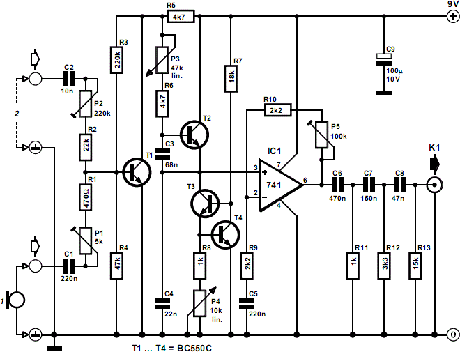
Nowadays, the speech quality on our telephone systems is generally very good, irrespective of distance. However, there are occasions, for instance, in an amateur stage production, or just for fun, when it is desired to reproduce the speech quality of yesteryear. The eroder circuit accepts an acoustic (via an electret micro-phone) or electrical signal. The signals are applied to the circuit inputs via C1 and C2, which block any direct voltage. The input cables should be screened. The signals are brought to (about) the same level by variable potential dividers P1-R1-R4 and P2-R2-R3, and then applied to the base of transistor T1. The level of the combined signals is raised by this preamplifier. The preamplifier is followed by an active low-pass filter consisting of T2–T4, C3, C4, R6–R8, and P4.


Although, strictly speaking, P3 serves merely to adjust the volume of the signal, its setting does affect the filter characteristic. Note, by the way, that the filter is a rarely encountered current-driven one in which C3 and C4 are the frequency-determining elements. It has a certain similarity with a Wien bridge. Transistors T3 and T4, and resistors R8 and P4 form a variable current sink. The position of P4 determines the slope of the filter characteristic and the degree of overshoot at the cut-off frequency. The low-pass filter is followed by an integrated amplifier, IC1, whose amplification is matched to the input of the electronic circuits connected to the eroder with P5. The final passive, third-order high-pass filter is designed to remove frequencies above about 300 Hz. The resulting output is of a typical nasal character, just as in telephones of the past.

Compressor For Electret Microphone

The ‘FM Remote Control Receiver’ (available on this website in Infra-red circuits section) has a connector where an analogue output is made available. To make a simple intercom or P.A. system the associated transmitter needs a microphone pre-amplifier that outputs a signal at the correct level. And that is exactly the function of this circuit. Actually, this design is adapted from a circuit published last year (‘AM Modulator for Intercom’). A few things have been changed so that it can work with the 5 V supply from the transmitter module. The OTA (IC1) used here is the single version (CA3080), which has slightly different characteristics from the dual CA3280.

The quad opamp is the same rail-to-rail TS924IN, made by ST. The turnover frequency of the filter (3rd order 1 dB Chebyshev) has been increased slightly to improve the intelligibility of speech and is now about 5.5 kHz. The filter now amplifies the signal by a factor of 10. In practice it is possible that due to various tolerances and the fact that the opamp is not perfect, the filter characteristic shows some deviation from that required. In our prototype it was necessary to change R15 into 2k7 to straighten the response curve. The DC current variation at the output of the OTA and the resulting offset variation at the output of current/voltage converter IC2d is such that the gain of IC2d has to be substantially smaller than in the ‘old’ design.

Otherwise the output could easily rise to the supply voltage at low signal levels. The value of R6 has therefore been made smaller by a factor of 10. This has reduced the gain of the circuit by 20 dB, which is compensated for in the filter. The amplitude of the signal from IC2d is fed back as a control current to the OTA by peak rectifier D1/C3 and inverting amplifier IC2b. R7 limits the loading on IC2d. P1 can be used to adjust the amplifier between a fixed gain and maximum compression. Figure A shows clearly what effect the circuit has. 0 dBr corresponds to 100 mV. The maximum gain, with P1 set to maximum compression, is about 48 dB (250 Ω) for small signals.

The minimum gain is about 20 dB (10 Ω). The OTA is then slightly overdriven and the distortion becomes several percent! With a fixed gain selected (P1 shorted) the gain is about 42 dB (125 ×). The middle curve was measured with P1 in its central position. The curve drawn for a fixed gain (the straight line) doesn’t finish at the edge of the graph because the end of the line corresponds to the maximum possible output level, which is 25 dBr (≈1.76 V or 5 / 2√2). Figure B shows the frequency response. The low turnover frequency is mainly determined by C8 (and to a lesser extent by C1) and is about 120 Hz.

The current consumption is about 7 mA When the circuit is battery powered we recommend the use of three AA cells, because the circuit still works perfectly at 4.5 V. If you want to use a higher supply voltage (maximum 12 V for the de TS924IN and 30 V for the CA3080, but you should also think of the voltage across the electret microphone!) you have to keep in mind that the maximum current through R9 (which is IABC) is only 2 mA. When we consider a maximum chosen current of 1 mA and the maximum output voltage of IC2b (half the supply voltage, which is 2.5 V), then the value of R9 should be (2.5 – 0.7) V / 1 mA = 1.8 kΩ. The value of 0.7 V corresponds to the potential between pin 5 and earth.

For a larger safety margin R9 is calculated with the full supply voltage and a current of 2 mA: (5 – 0.7) V / 2 mA = 2k2 (rounded upwards). Of course the regulation will then be different (a little less gain). This circuit and the transmitter module can therefore be fed from the same 5 V supply. Because the transmitter requires a DC offset at its input, a resistor is connected to +5 V via a jumper, which biases the output to half the supply voltage. With the jumper open R17 functions as a load resistor when the output is not connected, because C9 still has to charge up even without a load. If you’re designing a PCB for this compressor then it makes sense to include the transmitter module as well. The current consumption then increases by about 10 mA.