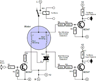
In single phase AC induction motors, often used in fridges and washing
machines, a start winding is used during the starting phase. When the
motor has reached a certain speed, this winding is turned off again. The
start winding is slightly out of phase to the run winding. The motor
will only start turning when the current through this winding is out of
phase to that of the run winding. The phase difference is normally
provided by placing a capacitor of several µF in series with the start
winding. When the motor reaches a minimum speed, a centrifugal switch
turns off the start winding.
The circuit diagram doesn’t show a centrifugal switch; instead it has a triac that is turned on during the staring phase. For clarity, the series capacitor isn’t shown in the diagram. Once the motor turns it will continue to do so as long as it isn’t loaded too much. When it has to drive too heavy a load it will almost certainly stall. A large current starts to flow (as the motor no longer generates a back EMF), which is limited only by the resistance of the winding. This causes the motor to overheat after a certain time and causes permanent damage. It is therefore important to find a way to detect when the motor turns, which happens to be surprisingly easy. When the motor is turning and the start winding is not used, the rotation induces a voltage in this winding.
The circuit diagram doesn’t show a centrifugal switch; instead it has a triac that is turned on during the staring phase. For clarity, the series capacitor isn’t shown in the diagram. Once the motor turns it will continue to do so as long as it isn’t loaded too much. When it has to drive too heavy a load it will almost certainly stall. A large current starts to flow (as the motor no longer generates a back EMF), which is limited only by the resistance of the winding. This causes the motor to overheat after a certain time and causes permanent damage. It is therefore important to find a way to detect when the motor turns, which happens to be surprisingly easy. When the motor is turning and the start winding is not used, the rotation induces a voltage in this winding.
This voltage will be out of phase since the winding is in a
different position to the run winding. When the motor stops turning
this voltage is no longer affected and will be in phase with the mains
voltage. The graph shows some of the relevant waveforms. More
information can be found in the application note for the AN2149 made by
Motorola, which can be downloaded from their website at
www.motorola.com. We think this contains some useful ideas, but keep in
mind that the circuit shown is only partially completed. As it stands,
it certainly can’t be put straight to use. We should also draw your
attention to the fact that mains voltages can be lethal, so take great
care when the mains is connected!

Tidak ada komentar:
Posting Komentar