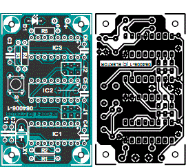
This little aid was originally designed to test the Shutter Time Meter.
This meter was specifically designed for ‘analogue’ SLR cameras. In
order to measure the exposure time of a camera accurately, it will first
have to be checked with a well-defined signal first. This circuit was
designed for that purpose. But the circuit can also be used if you need a
well-defined pulse for some other purpose. The circuit is build around a
trio of standard logic ICs. Firstly a 74HC4060 (IC1) is used to provide
a quartz crystal accurate reference for the duration of the pulses. For
the crystal frequency we choose the common 4.096 MHz value.
To test all the ranges of the shutter time meter, we choose three
different pulse lengths in three different decades, namely: 1 / 2 / 4 /
10 / 20 / 40 / 100 / 200 / 400 ms. With jumper J1 you select a frequency
of 1000, 500 or 250 Hz (see table). The frequency is then passed on to
J2 and the dual decade counter IC2 (a 4518). This does not need to be a
fast HC-type, since the frequency is at most 1 kHz. With J2 the
frequency can be reduced by 1, 10 or 100 times. This frequency is then
applied to IC3 (a 5-stage Johnson-counter). This has been set up in such
a way that in the end there appears only one single pulse at the
output.
The advantage of the Johnson-counter is that each output is free from
glitches and has a duration that is exactly equal to the period of the
clock input. We choose Q2 as the output. Q4 is used to stop the counter.
Q0 is only active if we push the reset-button S1. IC3 will then start
to count. To ensure that the reset does not affect the duration of the
pulse, a differentiating RC-network R4/C3 generates a short reset pulse.
R3 ensures that C4 is discharged after releasing S1. Also, just to be
sure, we don’t use the second counter output but use the third one
instead. For the same reason, to stop the counter we use the fifth
output.
Especially with longer times you will notice that the pulse will arrive
at the output a short time after pressing the switch. R5 drives a
current of nearly 20 mA through D1. D1 provides sufficient light for
this application to trigger the receiver diode in the shutter time
meter. An unusually fast type was selected for the LED, which, with a
switching time of 40 ns, has practically no influence on the length of
the pulse. If you would like to use another LED then you will have to
look closely at the switching time.
This needs to be small compared to the duration of the pulse. If you want to use the circuit with a logic level output then you can just omit D1. If necessary, the pulse lengths can be changed be selecting another crystal frequency. The current consumption in the idle state is less than 2 mA. In our prototype, while the circuit is delivering a pulse, the current consumption increases briefly to about 18 mA. Do not forget the wire link under IC2 when assembling the circuit.
Resistors
R1 = 1k
R2,R3 = 1M
R4 = 10k
R5 = 180
Capacitors
C1,C2 = 33pF
C3 = 10nF
C4,C5,C6 = 100nF ceramic, lead pitch 5mm
Semiconductors
D1 = HSDL-4230
IC1 = 74HC4060
IC2 = 4518
IC3 = 74HC4017
Miscellaneous
S1 = pushbutton, make contact, 6mm
J1,J2 = 3-way pinheader with jumper
X1 = 4.096MHz quartz crystal 1 wire link.


Tidak ada komentar:
Posting Komentar